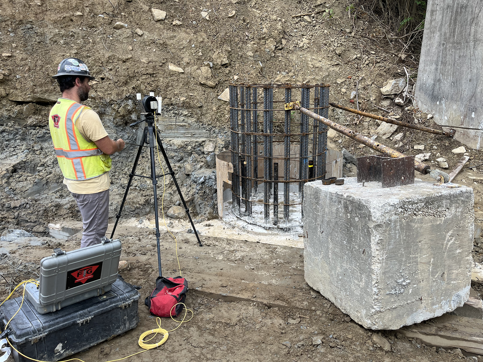
What is a Cross-Hole Sonic Logging test?
A Cross-Hole Sonic Logging (CSL) test, also known as a sonic logging test or ultrasonic cross-hole test, is a non-destructive method for evaluating and determining the structural integrity of concrete piles, concrete drilled shafts and other deep foundation elements.
CSL testing uses an ultrasonic transmitter and receiver that are lowered and lifted in unison within water-filled tubes to test the concrete between the tubes. The ASTM D6760 standard test method governs CSL integrity testing. The CSL testing procedure can detect anomalies inside concrete within minutes of the test being performed. Cross-Hole Tomography (CT) is a higher resolution analysis which can be used for further investigations after CSL has detected a flaw.
The staff at Haydon Bridge Company will order a CSL test to ensure that the concrete in a drilled shaft is uniform, meaning that it is of good quality from top of the shaft to the bottom or rock base. We also order them when the project contract specifications require it, and often, our experience with CSL Testing offers us an advantage when bidding this type of work. We subcontract the testing to a third-party consultant who is certified and experienced in CSL testing and accurate reporting. Specifically, we’ve been working with Foundation Test Group (FTG) of Owings Mill, MD for the last fifteen years.
During the CSL test analysis and reporting phase, FTG leads from the front. Rather than just noting the presence of an anomaly or defect, we seek to determine how it occurred, how to prevent its reoccurrence, and how to solve the foundation issues caused by its creation. FTG’s Chief Engineer has performed Cross-Hole Sonic Logging since 1996. Mr. Jeff Goodwin, P.E. is a recognized expert in the field and has made numerous presentations on CSL testing, foundation NDE, and drilled shaft remediation for the ADSC, DFI & ASCE.
Why use Cross Hole Sonic Logging testing over other testing?
Crosshole sonic logging (CSL) testing has several benefits, including:
- Locating defects: CSL can detect defects in the shaft center and between tubes, which Gamma-Gamma tests cannot. CSL can show the depth, extent, and approximate location of damage in a drilled shaft or pile.
- Speed: CSL is faster than other tests.
- Cost: CSL is cheaper than other tests.
- Safety: CSL is safer than Gamma-Gamma tests and doesn’t require special precautions.
- Accuracy: CSL testing is a reliable and accurate method for assessing the integrity of deep foundation elements, and is considered more accurate than sonic echo testing.
CSL testing is quicker, cheaper, more accurate, and safer than other methods.
What is the process of preparing for CSL Testing?
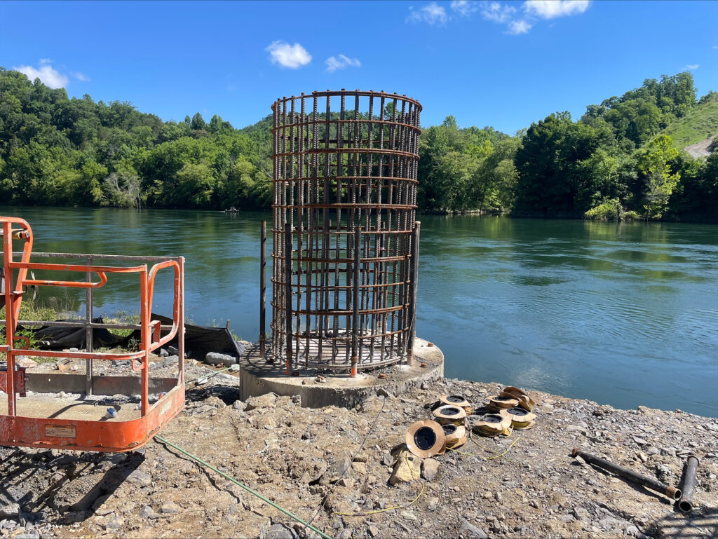
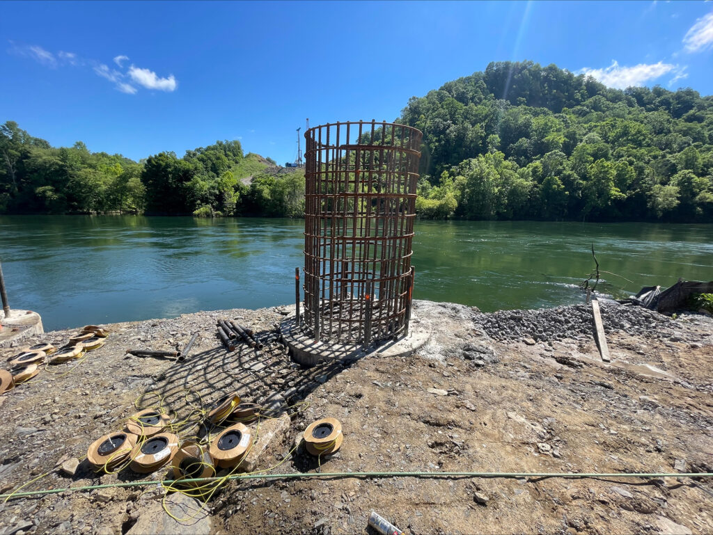
Prior to the CSL Testing by FTG, the team at Haydon Bridge Company must first construct the drilled shafts. Using specialized drilling equipment, cylindrical shafts are drilled into the ground and filled with rebar and concrete. These shafts can vary in diameter from 4’ to 8’ or more and can extend into the ground 40’+. Once the shafts are drilled, the rebar cages are constructed and placed into the shafts. For CSL Testing, 2” diameter steel tubes are tied to the inside edge of the rebar cage. The top of the CSL Tubes remain several feet above the top of the shaft for accessibility, while the bottom of the tubes extends to the bottom of the shaft. Once the rebar cage is placed, the tubes are filled with water and capped in preparation for the concrete pour. After the concrete is poured, it must cure for a minimum of 72 hours and reach a minimum strength of 2500 psi before CSL Testing can commence.
After the test is completed, the holes are filled with grout. Filling the access tubes immediately after casting the concrete avoids “debonding” of the tube, and is particularly important for PVC tubes. Steel tubes are preferred for CSL testing of wet cast shafts.
How is the data for the CSL report gathered?

The test involves lowering ultrasonic probes through the access tubes along the length of the foundation element and recording the passage of the probes as they are pulled to the surface. Scanning different tube combinations for the entire shaft allows the user to evaluate concrete quality and defect location along the length and by quadrant.
CSL testing utilizes an ultrasonic pulse traveling between a source and receiver probe as each probe passes through a water‐filled steel tube. The equipment measures wave travel times and receiver response energy, as well as to calculate the corresponding wave velocity. During CSL testing, readings are made as the source and receiver are withdrawn from the tubes and read at a specified interval of (0.2 ft.) Readings are made between adjacent pairs and diagonal pairs of tubes. Due to constraints from the geometry of the access tubes, the test is used to measure the quality of the concrete between the tubes.
The basic principle of CSL analysis is to look for unusual drops in the measured wave velocity (increases in travel time) of the concrete in a given CSL log of velocity versus depth. These localized drops are referred to in the Federal Highway Administration (FHWA) document as “anomalies”.
As stated in the FHWA document, “Strong anomalies in travel time (or velocity), combined with decreased signal strength, are interpreted as potential defects (flaws)”.
It is important to differentiate the velocity of the shaft as a whole (baseline velocity) from the reduced velocity measured in an anomaly zone. Velocity from the CSL test is used to determine the consistency of the concrete and the absence or presence of defects or anomalies within the shaft, not the strength of the concrete.
There are two ways to come up with a baseline velocity:
- The first is to compute a “theoretical velocity” based on the concrete strength. This method has a significant limitation in that there are a number of factors which will cause the actual velocity for a shaft to vary from the computed (theoretical) velocity. Some factors include the mix materials (especially aggregate used) and the design strength of the concrete. The design strength and actual strength of the concrete will often times differ greatly. In addition, the actual strength changes over time as the concrete continues to cure.
- The second way is to compute a “running average” of the velocity of the logged data, and use it as the baseline to compare the velocity of any anomaly zones. This is a far more accurate method to measure velocity. The advent of commercially available CSL systems now compute the average velocity automatically and reports these findings in a results table.
“Alternatively, some of the signal processing software now available will compute a running average of velocity over a specified depth interval (typically 10 to 12 ft) and compare individual readings to this baseline.” – FHWA
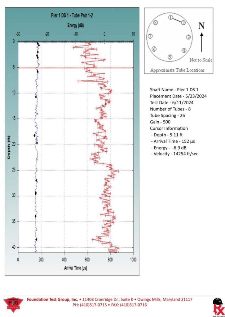
The graphs below show the velocity, arrival time, and energy of the wave from the transmitter probe in tube 1 to the receiver probe in tube 2. These measurements were in the proper ranges, which means the shaft had no anomalies between the two tubes shown. Other combinations of tubes are also tested and similar graphs are produced to show the quality of the concrete between those tubes.

How are CSL Testing Recommendations Facilitated?
The CSL test results search for changes in concrete wave speed, which is attributed to changes in concrete quality or strength due to the presence of a defect.
If an anomaly or defect is found (such as soil intrusions, necking, sand lenses, voids, etc.), additional testing may be required, for example Cross-Hole Tomography can be used. The ability given by Cross-Hole Tomography testing and analysis is the ability to see the shape of an anomaly to better judge its extent and severity between each tested tube pair. Once the report verifies presence of anomalies, our team will meet with FTG to discuss remediation of any defects to ensure the stability and strength of the drill shaft. Structures supported by drilled shafts have less redundancy and thus higher risk. It is critical that each shaft perform satisfactorily.
Shafts with no defects, or defects across the entire cross-section requiring replacement or repair, need no further analysis of the data. An automated Defect Analysis can assess the CSL data for concrete wave speeds (and hence concrete quality) and provides numeric and graphical presentations when defects are found. Shafts with local partial defects can be analyzed by 3D tomography to give clear visual spatial presentations of defects, allowing more effective remediation or analysis by the structural engineer.
Is CSL Testing Legally Required?
CSL testing is not legally required in Kentucky on any bridge or road construction project. However, if CSL Testing is conducted, Kentucky Department of Transportation has stated these guidelines:
“Cross-Hole Sonic Logging (CSL) is a nondestructive method to test the integrity of drilled shafts. The Contractor will be responsible for supplying all equipment and materials necessary to perform this testing, and obtaining the services of a CSL Testing Firm using personnel experienced with CSL testing and approved by the Engineer to perform the testing. The CSL tests must either be performed by or under the supervision of a responsible licensed professional engineer with:
- a minimum of three (3) years experience performing CSL tests, and
- experience performing CSL tests on a minimum of three (3) past projects with a scope and complexity similar to this project including a minimum of 60 drilled shafts in the past three (3) years.”
Haydon Bridge Company’s first priority in any project is the safety of our workers and the community; as well as the endurance and lifespan of our building projects. Thus, while not required, we order, prepare and evaluate a CSL test report whenever we suspect or want to determine any anomalies in a drift shift or concrete pour. The accurate and detailed reporting presented to us by the third-party engineering group, Foundation Test Group is used to determine next steps for the highest quality and safest roadway or bridge. And we are one of the very few or possibly the only Road & Bridge Construction company in Kentucky to have experience preparing, ordering and reading the CSL Testing method.
About Foundation Test Group:
Foundation Test Group (FTG) is a certified Women-Owned (WBE) engineering and testing company networked to support design and construction projects for a diverse group of Engineers, Architects, and Contractors as well as multiple state and local governments. Their firm seeks new relationships with teaming partners to provide state of the art support in a strong, but niche market.
From a recent FTG report, “CSL testing provides assurance that the foundation concrete is sound with no defects such as soil intrusions, necking, sand lenses, voids, etc. The extent, nature, depth, and approximate lateral location of a defect(s) can be determined with the CSL method. The method sends a sound wave between the source and receiver tubes to determine the wave speed of the matrix. This wave speed plot is then analyzed to determine if low velocity voids, defects or anomalies are encountered.”
We at Haydon Bridge Company especially enjoy working with FTG for our CSL testing needs because they are always prepared and knowledgeable regarding the various aspects of the process, especially the prevention and remediation of anomalies. In addition, they are always prompt with communication and great to get along with.
Case studies of CSL Study: US 127 Over the Cumberland River – Russell County, KY
Thus far, we have had successful CSL test on all of the shafts that have been constructed at the bridge for US127 over the Cumberland River. The shafts were expertly constructed and passed CSL testing with no anomalies detected. As the project proceeds, more shafts with CSL testing will be constructed.
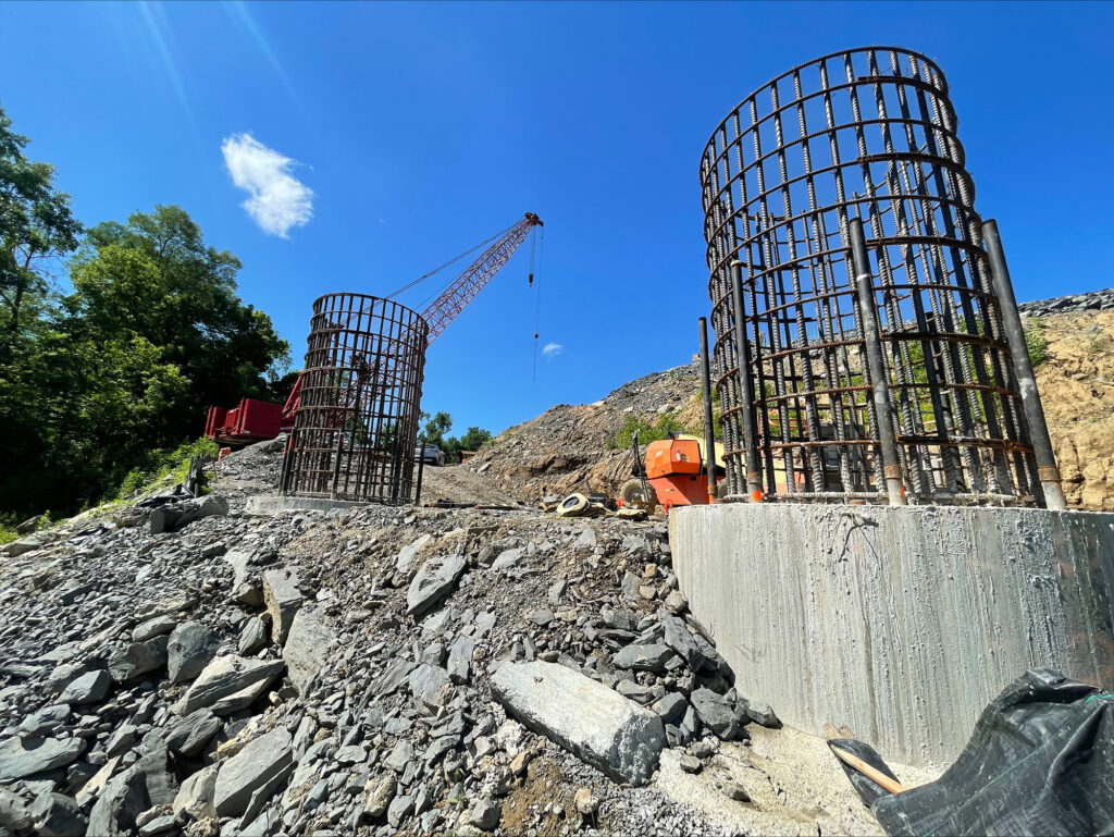
8’ Diameter drilled shafts for one of the piers on the Cumberland River Bridge on US127. These shafts extended approximately 40’ into the ground into solid bedrock. CSL testing was required as part of our contract with the KYTC. These shafts passed CSL testing and were accepted with no required remediation. Three more sets of these 8’ diameter shafts are being constructed, with two sets being constructed in the river itself.
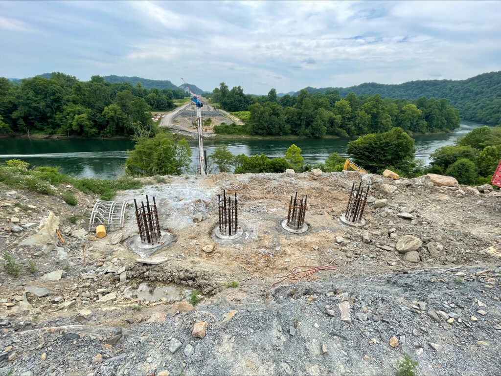
4’ Diameter drilled shafts for one of the abutments on the Cumberland River Bridge on US127. These shafts extended approximately 20’ into the ground into solid bedrock. CSL testing was required as part of our contract with the KYTC. All of these shafts passed CSL testing and were accepted with no required remediation.
KY 555 Over Long Lick Creek – Washington County, KY
Thus far, we have had successful CSL test on all of the shafts that have been constructed at the bridge for KY 555 over Long Lick Creek in Washington County, KY. These two shafts were expertly constructed and passed CSL testing with no anomalies detected.

6’ Diameter drilled shafts for the piers at the KY555 over Long Lick Creek Bridge. These shafts extended over 20’ into the ground into solid bedrock. CSL testing was required as part of our contract with the KYTC. Both of these shafts passed CSL testing and were accepted with no required remediation.

